If you've ever stared at a blank screen trying to explain a system design to your team, you already know why UML diagram code examples matter. Text-based UML lets you define diagrams using simple syntax no drag-and-drop tools, no expensive software. You write a few lines of code, and a visual diagram appears. For software engineers who live in their code editors, this is the fastest way to document architecture, plan features, and communicate designs without breaking flow.
What Does It Mean to Write UML Diagrams as Code?
UML diagrams as code means expressing your diagram structure in plain text using a domain-specific language. Instead of drawing boxes and arrows manually, you write declarations like class Customer { name: String } or Alice -> Bob: send request. A parser then renders this into a visual diagram. Tools like PlantUML and Mermaid are the most popular options. This approach keeps diagrams version-controlled, easy to update, and tightly coupled with your source code.
Understanding the basics of UML diagram code syntax is the starting point. Once you know how a language structures its elements, you can apply the same pattern across different diagram types.
Which UML Diagram Types Can You Write as Code?
Not every diagram type is equally supported across tools, but here's what you can typically express:
- Class diagrams show classes, attributes, methods, and relationships
- Sequence diagrams model interactions between objects over time
- Use case diagrams capture actor-goal relationships
- Activity diagrams describe workflows and business processes
- State diagrams represent object states and transitions
- Component diagrams illustrate system components and dependencies
- Deployment diagrams map software to hardware infrastructure
How Do You Write a Class Diagram in PlantUML?
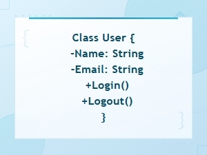
Class diagrams are the most common UML diagram in code form. Here's a straightforward PlantUML example:
@startuml
class User {
 -id: int
 -name: String
 -email: String
 +login(): void
 +logout(): void
}

class Order {
 -orderId: int
 -total: double
 -status: String
 +calculateTotal(): double
 +cancel(): void
}

class Product {
 -productId: int
 -title: String
 -price: double
}

User "1" -- "" Order : places >
Order "" -- "" Product : contains >
@enduml
This generates a diagram showing three classes with their attributes, methods, and relationships. The "1" -- "" notation defines multiplicity one user places many orders.
How Do You Write a Sequence Diagram in PlantUML?
Sequence diagrams show how objects talk to each other. They're especially useful for modeling API calls, authentication flows, or any multi-step interaction. Here's an example of a basic login flow:
@startuml
actor User
participant "Login Page" as LP
participant "Auth Service" as AS
participant "Database" as DB

User -> LP: enter credentials
LP -> AS: authenticate(email, password)
AS -> DB: query user by email
DB --> AS: user record
AS --> LP: JWT token
LP --> User: redirect to dashboard
@enduml
The arrows show the direction of communication, and the return arrows (-->) indicate responses. If you want to go deeper on notation rules, check this sequence diagram code notation guide.
How Do You Write an Activity Diagram in PlantUML?
Activity diagrams are great for mapping workflows. Think order processing, onboarding steps, or deployment pipelines. Here's an example:
@startuml
start
:Customer submits order;
if (Payment valid?) then (yes)
 :Reserve inventory;
 if (Items in stock?) then (yes)
 :Process shipment;
 :Send confirmation email;
 else (no)
 :Notify customer of delay;
 :Backorder items;
 endif
else (no)
 :Show payment error;
 :Prompt retry;
endif
stop
@enduml
The syntax reads almost like pseudocode. Decision points use if/else/endif, and start / stop mark the beginning and end of the flow.
Can You Write a Use Case Diagram as Code?
Yes, though use case diagrams are simpler in structure. Here's a basic example:
@startuml
left to right direction
actor Customer
actor Admin

rectangle "Online Store" {
 usecase "Browse Products" as UC1
 usecase "Place Order" as UC2
 usecase "Manage Inventory" as UC3
 usecase "Generate Reports" as UC4
}

Customer --> UC1
Customer --> UC2
Admin --> UC3
Admin --> UC4
UC2 ..> UC1 : <>
@enduml
Use case diagrams communicate scope. They show who does what without getting into implementation details useful during early planning or stakeholder discussions.
What About State and Component Diagrams?
State diagrams track how an object changes over its lifecycle. Here's one for an order:
@startuml
[] --> Pending
Pending --> Processing : payment confirmed
Pending --> Cancelled : user cancels
Processing --> Shipped : items dispatched
Shipped --> Delivered : delivery confirmed
Delivered --> []
Cancelled --> []
@enduml
Component diagrams map your system's architecture at a higher level:
@startuml
package "Frontend" {
 [Web App]
 [Mobile App]
}

package "Backend" {
 [API Gateway]
 [Auth Service]
 [Order Service]
}

database "Data Layer" {
 [PostgreSQL]
 [Redis Cache]
}

[Web App] --> [API Gateway]
[Mobile App] --> [API Gateway]
[API Gateway] --> [Auth Service]
[API Gateway] --> [Order Service]
[Order Service] --> [PostgreSQL]
[Auth Service] --> [Redis Cache]
@enduml
These kinds of diagrams are common in system design interviews, onboarding docs, and architecture decision records.
What Are the Most Common Mistakes When Writing UML Code?
- Overloading a single diagram. Don't try to fit every class, every relationship, and every method into one diagram. Split into focused views.
- Skipping relationship labels. An arrow without context is meaningless. Always label associations with verb phrases like
: places >or: sends >. - Using wrong arrow syntax. In PlantUML,
--means association,--|>means inheritance, and..>means dependency. Mixing these up creates misleading diagrams. - Ignoring multiplicity. Saying "User has Orders" is vague. Specifying
"1" -- ""removes ambiguity. - No version control. Since diagrams are plain text, store them in your repo alongside code. Diagrams that live in separate tools get outdated fast.
- Writing diagrams without a purpose. Every diagram should answer a question: "How does auth work?" "What happens when an order fails?" If it doesn't clarify something, skip it.
When Should You Choose Text-Based UML Over Visual Tools?
Text-based UML fits best when:
- Your team uses Git and wants diagrams in pull requests
- You need to update diagrams frequently as code changes
- You prefer keyboard-driven workflows
- You want to embed diagrams in documentation sites or Markdown files
- You don't want to pay for diagramming licenses
Visual tools still have their place especially for quick whiteboard-style sketches or when non-technical stakeholders need to edit diagrams. But for engineering documentation, code-based diagrams win on speed and maintainability.
You can also use an online UML diagram code generator tool to preview your output before committing it to your project.
What Tips Help You Write Better UML Code?
- Start with one diagram type. Class diagrams or sequence diagrams are the easiest entry points. Master one before moving on.
- Use aliases for readability. In PlantUML,
participant "Auth Service" as ASkeeps your code clean. - Add notes for context. Use
note right of ClassName: descriptionto explain non-obvious design decisions. - Group related elements. Use
package,namespace, orrectangleblocks to visually cluster related components. - Render often. Don't write 200 lines and then check. Render after every few lines to catch syntax errors early.
- Keep a diagram index. Maintain a list of diagrams with their purpose and location in your repo. This helps new team members find what they need.
Practical Checklist for Your Next UML Diagram
- Pick the diagram type that answers your specific question
- Choose a tool (PlantUML for broad support, Mermaid for Markdown-native workflows)
- Write the code in a
.pumlor.mmdfile inside your repo - Render and verify the output looks correct
- Label all relationships and include multiplicity
- Add notes for design decisions that aren't obvious from the diagram alone
- Commit the file alongside your code changes
- Link the diagram in your team's documentation or README
Start with a single class diagram for a feature you're building right now. Write the code, render it, share it with your team, and iterate. That one habit expressing designs as version-controlled code will improve how your team communicates about software architecture over time.
 Uml Diagram Code Syntax Guide for Diagram Languages
 Uml Diagram Code Guide for System Architects – Languages and Tools
 Sequence Diagram Code Notation Guide
 Flowchart Code Syntax: a Beginner's Guide
 Mermaid Flowchart Syntax Examples and Usage
 Plantuml Sequence Diagram Syntax and Notation Reference Guide