If you've ever sat in a design review and watched a room full of engineers stare at a whiteboard diagram that nobody fully understands, you already know why UML diagram code for system architects matters. Diagrams drawn by hand or in a GUI tool get outdated fast, live in one person's desktop, and become impossible to version control. When you express your system design as code text that generates the diagram you solve most of those problems at once. Your diagrams become reproducible, trackable in Git, reviewable in pull requests, and easy to update when requirements shift.
What does "UML diagram code" actually mean?
UML diagram code is a plain-text notation that describes a software system's structure or behavior using the Unified Modeling Language (UML) standard. Instead of dragging boxes around on a canvas, you write short declarations that a rendering tool converts into a visual diagram. Popular text-based formats include PlantUML, Mermaid, and Structurizr DSL, each with its own syntax but all producing standard UML output like class diagrams, component diagrams, and deployment views.
For system architects, this approach turns a static picture into a living artifact. You store the source text alongside your architecture decision records, run a build step that generates updated images, and everyone on the team always sees the current state of the design.
Why do system architects prefer diagram-as-code over GUI tools?
The short answer is control and collaboration. Here are the specific reasons most architects make the switch:
- Version control. Text files merge cleanly in Git. You can see exactly what changed in a diagram, who changed it, and when just like application code.
- Automation. You can generate diagram images in a CI pipeline, embed them in documentation sites, or trigger updates when a related file changes.
- Speed of iteration. Editing a few lines of text is faster than repositioning shapes, especially for large diagrams with 30 or more elements.
- Consistency. Templates and shared libraries of notation keep diagrams from drifting into personal style. New team members read diagrams that all follow the same conventions.
- Portability. A PlantUML or Mermaid file is plain text. It works in any editor, any OS, any documentation platform that supports rendering.
Which UML diagram types do architects write as code most often?
Not every UML diagram translates equally well to a text format. System architects tend to reach for code-based approaches when the diagram needs to live alongside other documentation and evolve over time. The most common types expressed as code include:
Component diagrams
These show the high-level building blocks of a system services, libraries, databases and how they connect. For architects defining a microservices layout or a layered monolith, a component diagram in code is usually the starting point. It maps directly to deployment boundaries and team ownership.
Sequence diagrams
When you need to show how a request flows through multiple services, a sequence diagram written in code notation is far easier to maintain than a hand-drawn version. If a message order changes, you edit a few lines instead of redrawing arrows.
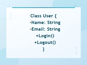
Class diagrams
Useful during domain modeling phases, class diagrams in code let architects define entities, value objects, and relationships as structured text. Tools can even generate these from source code, but architect-authored versions capture the intended design rather than the current implementation.
Deployment diagrams
Infrastructure architects use deployment diagrams to show nodes (servers, containers, cloud regions) and artifact placement. When your infrastructure is defined in code already (Terraform, CloudFormation), keeping the architecture diagram in a similar text format feels natural.
Container diagrams (C4 model)
Though not strictly UML, many architects combine UML diagram code tools with the C4 model for system context and container-level views. PlantUML and Structurizr both support C4 notation, letting architects express scope at multiple zoom levels.
What does a practical example look like?
Here is a simple PlantUML component diagram that an architect might write to describe an order processing system:
@startuml

component "API Gateway" as gateway

component "Order Service" as orders

component "Inventory Service" as inventory

component "Payment Service" as payments

database "Orders DB" as odb


gateway --> orders : REST

orders --> inventory : gRPC

orders --> payments : async (Kafka)

orders --> odb

@enduml
This text produces a clean, labeled diagram with directional arrows showing communication protocols. A reviewer can read the raw text in a pull request, understand the architecture, and suggest changes all without opening a diagramming tool.
You can find more detailed UML diagram code examples for software engineering that cover more complex scenarios, including multi-region deployments and event-driven architectures.
Where does UML diagram code fit in the architecture workflow?
Most architects who adopt diagram-as-code follow a workflow like this:
- Sketch on paper or whiteboard. The first pass is always rough. You need spatial thinking to explore options before committing to notation.
- Write the code version. Translate the sketch into PlantUML, Mermaid, or your chosen syntax. This forces you to be precise about names, relationships, and directionality.
- Render and review. Generate the image, share it with the team, and gather feedback. Because the source is text, reviewers can comment on specific lines.
- Merge and automate. Commit the diagram source to the repository. Set up a CI step that regenerates images on every push so documentation stays current.
- Revisit on change. When a service boundary shifts or a new integration appears, update the code not the whole diagram. Small edits produce accurate results.
What mistakes do architects make when writing UML diagram code?
Knowing the common pitfalls saves you from diagrams that confuse rather than clarify:
- Packing too much into one diagram. A single component diagram with 40 components is hard to read in any format. Split it into focused views one per bounded context or deployment environment.
- Using inconsistent naming. If your code calls a service "OrderSvc" in one diagram and "OrderService" in another, readers lose trust in the diagrams. Agree on a naming convention and stick to it.
- Skipping directionality. Arrows in UML have specific meanings. An open arrowhead means something different from a filled one. When writing code, make sure you pick the correct arrow syntax for the relationship you mean.
- Not storing diagrams near the code they describe. Diagrams buried in a Confluence page nobody updates are no better than whiteboard photos. Keep diagram source files in the same repository as the system they describe.
- Ignoring rendering differences. PlantUML and Mermaid render the same conceptual diagram differently. Pick one tool per project and document that choice so diagrams look consistent.
How do you pick the right text-based UML tool?
The tool you choose depends on your ecosystem and audience. A few practical considerations:
- PlantUML supports the widest range of UML diagram types and has a large plugin ecosystem. It works well if your team needs class, state, or activity diagrams in addition to the typical architecture views.
- Mermaid renders natively in GitHub, GitLab, and many Markdown-based documentation platforms. If your docs live in a wiki that supports Mermaid blocks, you get diagram rendering with zero extra tooling.
- Structurizr DSL is purpose-built for the C4 model and forces a clear separation of system context, containers, components, and code. It's a strong choice if your organization has adopted C4 as a standard.
- D2 is a newer option that generates diagrams from declarative code with automatic layout. It handles large, complex graphs better than some older tools.
Whichever tool you pick, make sure the team agrees on it before you have 50 diagrams in three different formats.
What are the real limitations?
Diagram-as-code is not perfect for every situation. Free-form spatial layouts where the physical position of a box on the page carries meaning are hard to express in text. Some architects also find that fine-tuning the visual appearance (colors, fonts, spacing) takes more effort in code than in a GUI tool like draw.io or Lucidchart. And for stakeholder-facing presentations where visual polish matters, you may still want to export the code-generated diagram into a design tool for final touches.
These are honest trade-offs. The key question is whether your primary audience is engineers who need accuracy and freshness, or executives who need a polished slide. For the former, diagram-as-code wins. For the latter, you might use both approaches in parallel.
How do you make UML diagram code part of your team's practice?
Adopting diagram-as-code is easier when you start small and build momentum:
- Pick one upcoming design review and produce the diagram in PlantUML or Mermaid instead of a GUI tool.
- Share the rendered image and the source text side by side so people see both the output and how easy it is to edit.
- Add the diagram source file to your repo with a README explaining how to render it.
- Set up a simple CI step (a GitHub Action or GitLab CI job) that regenerates diagram images on commit.
- Gradually replace legacy diagrams as you touch those parts of the system. Don't try to convert everything at once.
Quick checklist before you commit your next architecture diagram
- Does the diagram answer one clear question? If it answers three, split it.
- Are component names consistent with your service catalog and codebase?
- Do arrow types match the actual communication pattern (sync, async, data flow)?
- Is the source file stored in the same repo as the system it describes?
- Did you add a comment block at the top of the file explaining the diagram's purpose, author, and last update date?
- Can a new team member read the raw text and understand the architecture without extra context?
Start with one diagram this week. Write it as code, commit it, and share the pull request with your team. You'll know within a single review cycle whether this approach works for your architecture practice.
 Uml Diagram Code Syntax Guide for Diagram Languages
 Uml Diagram Code Examples for Software Engineering Projects
 Sequence Diagram Code Notation Guide
 Flowchart Code Syntax: a Beginner's Guide
 Mermaid Flowchart Syntax Examples and Usage
 Plantuml Sequence Diagram Syntax and Notation Reference Guide