If you're building a database and need to communicate your schema to a team or even just to your future self ER diagram notation is the shared language that makes that possible. Developers use Entity-Relationship diagrams to map out tables, relationships, and constraints before writing a single line of SQL. Getting the notation right means fewer misunderstandings, cleaner schemas, and less time refactoring after deployment. Getting it wrong means misaligned teams, broken migrations, and models that don't reflect the real domain.
What exactly is ER diagram notation?
ER diagram notation is a set of visual symbols and conventions used to represent entities (things your application stores data about), their attributes (properties or columns), and the relationships between them. Think of it as a blueprint for your database. The most common notations you'll encounter as a developer are Chen notation, Crow's Foot notation (also called IE notation), and UML class diagram notation applied to data modeling.
Each notation style communicates the same core ideas tables, primary keys, foreign keys, cardinality but uses different shapes and line styles to do it. Picking the right one depends on your audience and your tooling.
Why should developers care about which notation they use?
Because diagrams are only useful if people actually read them. If your team uses Crow's Foot and you hand them a Chen-style diagram, you've added friction instead of removing it. Many ORMs, migration tools, and database design tools expect a specific notation. If you understand the notation your tools generate, you can read auto-generated diagrams and catch design issues early.
There's also a difference between logical and physical data model syntax that affects what notation details matter. A logical model might omit data types and focus on business relationships. A physical model needs to show column types, indexes, and constraints details that directly map to your SQL DDL.
What does Crow's Foot notation look like and why do developers prefer it?
Crow's Foot notation is the most common style in developer-facing tools like MySQL Workbench, dbdiagram.io, Lucidchart, and draw.io. It uses rectangles for entities, lines for relationships, and small symbols at the ends of lines to show cardinality:
- One-to-one: A single line on both ends
- One-to-many: A single line on the "one" side, a three-pronged "crow's foot" on the "many" side
- Many-to-many: Crow's feet on both ends (usually resolved with a junction table in implementation)
Each entity is a rectangle divided into sections: the entity name at the top, primary keys in the first section, and regular attributes below. Developers like this notation because it's compact, readable, and maps directly to what they see in database admin tools.
How does Chen notation differ from Crow's Foot?
Chen notation, the original ER model style proposed by Peter Chen in 1976, uses ovals for attributes, rectangles for entities, and diamond shapes for relationships. It's more academic and more verbose. You'll see it in textbooks and database courses, but rarely in production development workflows.
The main reason developers avoid Chen notation for day-to-day work is that it gets cluttered fast. A table with 15 attributes means 15 ovals connected by lines to the entity rectangle. That's hard to fit on a whiteboard, let alone a pull request. Crow's Foot packs the same information into a single rectangle with listed attributes.
What are the common cardinality and participation symbols?
Cardinality describes how many instances of one entity relate to another. Participation describes whether every instance must participate in a relationship (mandatory) or can exist without it (optional). Here's what these look like in Crow's Foot:
- Mandatory one: A single line with a perpendicular bar (the entity must have exactly one related instance)
- Optional zero or one: A single line with a circle (the entity may or may not have a related instance)
- One or many: Crow's foot with a perpendicular bar (at least one, possibly more)
- Zero or many: Crow's foot with a circle (none, or as many as needed)
Getting these symbols wrong is one of the most common sources of confusion. If a line shows "mandatory one" when you meant "optional zero or one," a junior developer reading your diagram will build the wrong constraints or worse, a senior developer will approve a migration with incorrect NOT NULL or FOREIGN KEY rules.
What about UML notation for data models?
UML class diagrams can represent the same information as ER diagrams. Entities become classes, attributes become class properties with visibility and types, and relationships use association lines with multiplicity markers like 1, 0..1, , or 1... If your team already uses UML for application architecture, extending it to your data layer can reduce the number of diagramming conventions you need to maintain. The tradeoff is that UML carries more overhead you might not need method compartments or visibility markers when you're just trying to show a database schema.
For a broader look at how notation choices differ across roles, including when architects use different conventions than developers, see this comparison of data model notation for architects.
How do developers actually use ER diagrams in their workflow?
Most developers don't draw ER diagrams by hand. They use tools that either let them design visually or generate diagrams from existing schemas. Here's how it typically works in practice:
- Design-first (schema planning): You sketch out entities and relationships before writing migrations. Tools like dbdiagram.io let you write a simple DSL and render a Crow's Foot diagram automatically.
- Reverse engineering: You connect a tool to an existing database and generate a diagram from the live schema. MySQL Workbench, DBeaver, and pgModeler all do this.
- Documentation: You embed ER diagrams in wikis, README files, or architecture decision records so new team members understand the data layer without reading every migration file.
Some teams also use SQL-based data model syntax examples alongside their diagrams to keep the visual and code representations in sync.
What mistakes do developers make with ER diagram notation?
Here are the errors that show up most often in code reviews and architecture discussions:
- Mixing notations in the same diagram: Using Crow's Foot for some relationships and Chen-style diamonds for others. This confuses readers and signals that the diagram wasn't created intentionally.
- Showing many-to-many relationships without a junction entity: In theory, a many-to-many relationship is valid in ER modeling. In implementation, you always need a join table. Your diagram should reflect what you're actually going to build.
- Ignoring cardinality and participation entirely: Lines without cardinality markers leave readers guessing. Is a relationship optional or required? If your diagram doesn't answer that question, it's not finished.
- No primary keys labeled: Every entity should clearly mark its primary key, usually with PK or by underlining the attribute. Without it, the diagram doesn't fully describe the schema.
- Overloading diagrams with every column: You don't always need to show every
created_attimestamp and soft-delete flag. Focus on the attributes that matter for understanding the relationships and domain logic.
Which tools handle ER diagram notation well?
A few tools that developers consistently reach for:
- dbdiagram.io Uses a simple text-based syntax to generate Crow's Foot diagrams. Great for quick schema sketches.
- MySQL Workbench Built-in ER diagramming with reverse engineering from live databases. Uses Crow's Foot notation by default.
- Lucidchart Supports multiple notation styles with templates. Good for teams that need diagrams in shared documents.
- Mermaid.js Renders ER diagrams from text in Markdown files. Useful for embedding in documentation and version control.
- DBeaver Free, open-source database tool that generates ER diagrams from connected schemas across many database engines.
Pick a tool your whole team can access and agree on. The notation standard matters less than consistency across your project.
Quick checklist for your next ER diagram
- ✅ Choose one notation style (Crow's Foot is the safest default for development teams)
- ✅ Label every primary key clearly
- ✅ Mark cardinality and participation on every relationship line
- ✅ Resolve many-to-many relationships into junction entities
- ✅ Include foreign key indicators so readers can trace references
- ✅ Keep attribute lists focused show what helps people understand the model, not every column
- ✅ Version your diagrams alongside your schema a diagram from three migrations ago is worse than no diagram
- ✅ Test readability by showing the diagram to someone unfamiliar with the schema if they can't follow it, simplify
 Uml Class Diagram Syntax Explained: Complete Data Model Guide
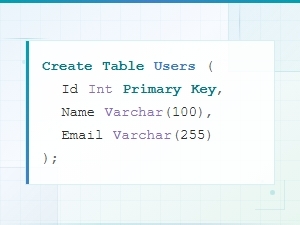 Sql Data Model Syntax Examples with Diagrams
 Data Model Notation Guide for Architects: Diagram Syntax Explained
 Logical vs Physical Data Model Diagram Syntax Explained
 Flowchart Code Syntax: a Beginner's Guide
 Mermaid Flowchart Syntax Examples and Usage