When you're designing object-oriented software, you need a way to communicate how your classes, attributes, and relationships fit together before writing a single line of code. That's exactly where UML class diagram syntax comes in. It gives you a standardized visual language to map out your system's structure so your whole team shares the same understanding. Getting the syntax right means fewer miscommunications, cleaner code architecture, and faster onboarding for anyone joining the project.
What is a UML class diagram?
A UML class diagram is a type of data model diagram used in software engineering to show the structure of a system. It displays classes as boxes divided into compartments, along with the relationships between those classes. Think of it as a blueprint for your object-oriented code it captures what your classes contain (attributes and methods) and how they connect (inheritance, association, composition).
The notation comes from the Unified Modeling Language (UML), which was created by Grady Booch, James Rumbaugh, and Ivar Jacobson and later standardized by the Object Management Group (OMG).
How do you read a class box in a UML diagram?
Every class in a UML class diagram is drawn as a rectangle with up to three compartments stacked vertically:
- Top compartment The class name, written in bold and centered. Abstract class names appear in italics.
- Middle compartment The attributes (fields or properties). Each attribute follows this pattern: visibility name : type [multiplicity] = default value.
- Bottom compartment The methods (operations). Each method follows: visibility name(parameters) : return type.
Here's what the visibility symbols mean:
- + public
- - private
- # protected
- ~ package
So when you see - name : String, it means a private attribute called "name" of type String. When you see + getFullName() : String, it means a public method that returns a String.
What do the different relationship lines mean?
Relationships between classes are drawn as lines (or arrows) connecting two class boxes. Each style has a specific meaning:
Association
A simple solid line between two classes. It means one class knows about or uses the other. You can label the line with the nature of the relationship and add multiplicity indicators like 1, 0.., or 1.. at each end.
Inheritance (Generalization)
A solid line with a hollow triangle arrowhead pointing from the child class to the parent class. This represents an "is-a" relationship for example, Dog inherits from Animal.
Implementation (Realization)
A dashed line with a hollow triangle arrowhead. This shows that a class implements an interface.
Aggregation
A solid line with an open (hollow) diamond at the "whole" end. It represents a "has-a" relationship where the part can exist independently of the whole like a Team has Players, but players can exist without the team.
Composition
A solid line with a filled (solid) diamond at the "whole" end. This is a stronger form of aggregation where the part cannot exist without the whole like a House has Rooms, and rooms don't exist without the house.
Dependency
A dashed line with an open arrowhead pointing from the dependent class to the class it depends on. This means a change in one class may affect the other.
What does multiplicity mean in a class diagram?
Multiplicity tells you how many instances of one class can be linked to an instance of another class. You place these numbers at either end of an association line. Common multiplicity values include:
- 1 exactly one
- 0..1 zero or one
- zero or more
- 1.. one or more
- n exactly n (a specific number)
For example, if a Customer can place many Orders, you'd write 1 on the Customer side and on the Order side of the association line.
What's a practical example of a UML class diagram?
Imagine you're modeling an online bookstore. You might have these classes:
Book with attributes - title : String, - isbn : String, - price : double, and methods + getPrice() : double, + applyDiscount(percent : double) : void.
Author with attributes - name : String, - bio : String.
Order with attributes - orderId : String, - date : Date, and methods + calculateTotal() : double.
Customer with attributes - email : String, - address : String.
The relationships would look like this:
- Customer to Order: 1 to (one customer places many orders)
- Order to Book: to (an order contains many books; a book can appear in many orders)
- Book to Author: to 1.. (a book has one or more authors; an author can write many books)
This kind of structure maps directly to code. If you later need to move from diagrams to actual tables, you can reference SQL data model syntax examples to translate your class structure into a database schema.
What are common mistakes when writing UML class diagram syntax?
- Mixing up aggregation and composition. Both use diamonds, but the hollow vs. solid distinction matters. Ask yourself: can the part exist without the whole? If yes, it's aggregation. If no, it's composition.
- Forgetting visibility markers. Leaving off +, -, or # makes your diagram ambiguous. Every attribute and method should show its access level.
- Overloading one diagram with every class. Large systems need multiple diagrams grouped by feature or module. One massive diagram is hard to read and maintain.
- Skipping multiplicity. Without multiplicity, developers don't know whether a relationship is one-to-one, one-to-many, or many-to-many. Always add it.
- Using inconsistent naming. Stick to one convention either camelCase or snake_case and keep class names as nouns and method names as verbs.
Tips for drawing cleaner class diagrams
- Start with your domain model, not your code. Identify real-world entities and their relationships first.
- Use a tool like PlantUML, Lucidchart, or draw.io to keep your diagrams consistent and easy to edit.
- Group related classes into packages and show package boundaries when diagramming large systems.
- Keep attribute types simple and recognizable (String, int, boolean, Date) avoid referencing implementation-specific types in early design stages.
- When your diagram connects to a database, compare it against your ER diagram notation to make sure both models stay aligned.
How does UML class diagram syntax compare to other diagram types?
UML class diagrams focus on static structure what classes exist and how they relate. They don't show the order of operations, data flow, or timing. If you need to show behavior, you'd use sequence diagrams or activity diagrams. If you're focused on database structure rather than object-oriented structure, an ER diagram is a better fit. Many projects use class diagrams and ER diagrams together class diagrams for application logic and ER diagrams for database design.
Quick checklist: UML class diagram syntax essentials
- ☐ Every class box has a name, attributes compartment, and methods compartment
- ☐ Abstract classes use italics for the class name
- ☐ All attributes and methods show visibility symbols (+, -, #, ~)
- ☐ Attributes follow the format: visibility name : type
- ☐ Methods follow the format: visibility name(params) : return type
- ☐ Relationship lines use the correct style (solid, dashed, diamond, triangle, arrowhead)
- ☐ Multiplicity is labeled on both ends of every association
- ☐ Diagram is organized by module or feature to stay readable
- ☐ Naming conventions are consistent across all classes
Next step: Pick one feature of a system you're currently building. Sketch out three to five classes with their attributes, methods, and relationships using the syntax rules above. Start rough, then refine the notation. If you also work with relational databases, check out how these class structures translate by looking at SQL data model syntax examples.
 Er Diagram Notation Guide for Developers: Syntax and Symbols Explained
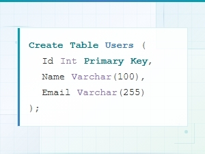 Sql Data Model Syntax Examples with Diagrams
 Data Model Notation Guide for Architects: Diagram Syntax Explained
 Logical vs Physical Data Model Diagram Syntax Explained
 Flowchart Code Syntax: a Beginner's Guide
 Mermaid Flowchart Syntax Examples and Usage